5 Arduino Projects to Build With Your Kids This Weekend
Five Arduino projects you can start and finish in a weekend, each with a full component list and build steps. Looking for more ideas across all age groups? See our Arduino projects with kids roundup.
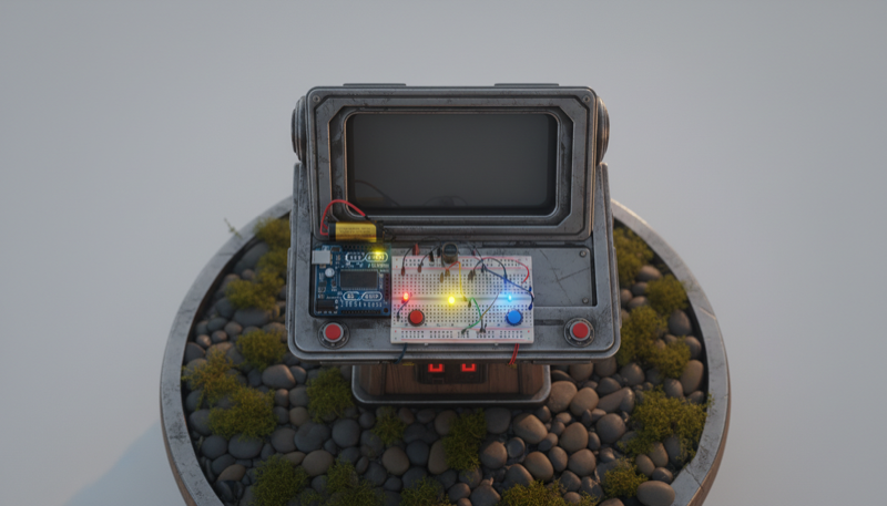
Memory Game Challenge
Build a classic 'Simon Says' memory game! This fun, interactive project uses an Arduino to create a sequence of lights and sounds. Your goal is to repeat the pattern by pressing the large, colorful arcade buttons in the correct order. The sequence gets longer with each successful round, challenging your memory. It's a fantastic project for learning basic programming concepts like arrays, loops, and functions, and is perfect for a weekend activity with kids.

A Simon Says game with arcade buttons and LEDs. The Arduino plays a sequence of lights and sounds, and you have to repeat the pattern. It gets longer every round.
Components:
- Arduino Uno R3
- 4x Large Arcade Push Buttons (different colors)
- 4x LEDs (matching button colors)
- 4x 220 ohm Resistors
- Piezo Buzzer
- Solderless Breadboard
- Jumper Wires
- USB Cable
Build it:
- Wire each of the 4 LEDs to its own GPIO output pin through a 220 ohm resistor
- Wire each arcade button to its own GPIO input pin using the Arduino's internal pull-up resistors
- Wire the piezo buzzer to a PWM-capable pin so it can play different tones for each color
- Install the Arduino IDE and create a new sketch
- Write the game logic: store the sequence in an array, add a random color each round, play the sequence by lighting LEDs and sounding tones, then read button presses and compare them to the stored sequence
- If the player gets it right, add another step to the sequence and speed up the playback slightly
- If they get it wrong, play a "game over" buzzer sound and flash all LEDs. Display the score (number of rounds) via Serial Monitor
- Mount the buttons and LEDs on a piece of cardboard or in a project box so it feels like a real arcade game
- Let the kids customize the tones and colors
Lightning Reaction Game
A fun and simple two-player game to test your reaction time. After a random delay, a central LED will light up. The first player to press their button wins! The winner's LED lights up and a victory tune plays. It's a great first project for learning about inputs, outputs, and simple game logic on the Arduino.
A two-player showdown. A central LED lights up after a random delay. First one to hit their button wins, and their LED lights up with a victory tune.
Components:
- Arduino Uno R3
- 2x Tactile Push Buttons
- 3x LEDs (1 central green, 2 player LEDs)
- 3x 220 ohm Resistors
- Piezo Buzzer
- Solderless Breadboard
- Jumper Wires
- USB Cable
Build it:
- Wire the central "Go" LED to a digital output pin through a 220 ohm resistor
- Wire each player's LED to its own output pin, each through a 220 ohm resistor
- Wire each player's push button to a digital input pin, using the Arduino's internal pull-up resistors
- Wire the piezo buzzer to a PWM pin for the victory tune
- Create a new sketch in the Arduino IDE
- Write the game logic: turn off all LEDs, wait a random delay (2 to 5 seconds), then light up the central LED. Read both buttons and the first one pressed wins
- Light up the winner's LED and play a short victory melody through the buzzer. If someone presses before the "Go" LED, count it as a false start and penalize them
- Add a round counter and keep score across multiple rounds via Serial Monitor
- Upload the sketch, open Serial Monitor, and test with a few rounds to make sure timing and scoring feel right
- Mount everything on a board or in an enclosure so the kids can really slap those buttons without knocking wires loose
OK-to-Wake Clock
A simple and fun weekend project to build with your child. This clock uses a strip of colorful LEDs to visually signal when it's an acceptable time to wake up the parents. During 'sleep time', the clock glows a soft red. At your pre-set wake-up time, it turns bright green, letting your child know it's okay to start the day. The wake-up time is easily adjustable with two push-buttons, making it a practical solution for reclaiming your weekend mornings.
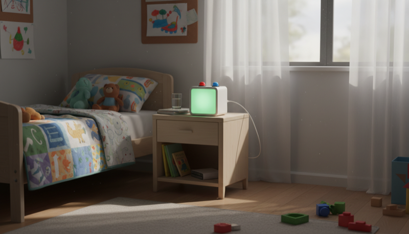
A clock that glows red during sleep time and turns green when it's OK to get up. Two buttons let you adjust the wake-up time without touching any code.
Components:
- Arduino Uno R3
- DS3231 Real-Time Clock (RTC) Module
- WS2812B Addressable LED Strip (short, 8-12 LEDs)
- 2x Tactile Push Buttons
- 2x 10K ohm Resistors (for pull-downs)
- Solderless Breadboard
- Jumper Wires
- USB Cable or Battery Pack
Build it:
- Wire the DS3231 RTC module to the Arduino via I2C: SDA to A4, SCL to A5, plus VCC and GND
- Wire the WS2812B LED strip: data pin to a digital output (e.g., pin 6), plus 5V and GND
- Wire two push buttons to digital input pins with pull-down resistors for adjusting the wake-up time (one button for hours, one for minutes)
- Install the Arduino IDE and add the RTClib and Adafruit NeoPixel libraries
- Write a sketch that reads the current time from the RTC module and compares it to the stored wake-up time
- Before the wake-up time, the LED strip glows soft red ("still sleeping"). At the wake-up time, it switches to bright green ("OK to get up")
- Pressing the buttons adjusts the wake-up hour and minute. Store the setting so it persists after power cycles
- Put the whole thing in a small enclosure or box next to your kid's bed, with the LED strip visible and buttons accessible on top
- No more 5 AM wake-up calls on Saturday mornings
Spooky Halloween Candy Bowl
A fun and interactive Halloween project perfect for kids and beginners. This candy bowl uses an ultrasonic sensor to detect when a hand reaches for a treat. Once triggered, an Arduino controller springs the trap: a hidden spider pops up on a servo motor, red LEDs flash menacingly, and a piezo buzzer emits a spooky screech. It's a simple, battery-powered jump-scare that's sure to be a hit with trick-or-treaters.

An ultrasonic sensor detects a hand reaching for candy. When it does, a hidden spider pops up on a servo, red LEDs flash, and a buzzer screeches.
Components:
- Arduino Uno R3
- HC-SR04 Ultrasonic Distance Sensor
- SG90 Micro Servo Motor
- 2x Red LEDs
- 2x 220 ohm Resistors
- Piezo Buzzer
- Plastic Spider (or other spooky prop)
- Solderless Breadboard
- Jumper Wires
- Battery Pack (6V or USB power bank)
Build it:
- Wire the HC-SR04 ultrasonic sensor: VCC to 5V, GND to GND, Trig to a digital pin, Echo to another digital pin
- Wire the SG90 servo signal to a PWM-capable pin, plus power and ground
- Wire both red LEDs to output pins through 220 ohm resistors
- Wire the piezo buzzer to a PWM pin for spooky sound effects
- Install the Arduino IDE and add the Servo library
- Write a sketch that continuously measures distance with the ultrasonic sensor. When a hand gets within range (say 10-15 cm), trigger the scare sequence
- The scare sequence: servo swings the spider up, red LEDs flash rapidly, buzzer plays a screech sound, then after a couple seconds the servo lowers the spider and everything resets
- Add a short cooldown so it doesn't retrigger immediately
- Mount the ultrasonic sensor pointing into the candy bowl, hide the servo and spider behind the bowl's rim, and tuck the Arduino and wires underneath
- Let the kids pick the scare sounds and adjust how close a hand needs to get before the trap springs
Plant Guardian
A fun and educational project that creates a 'smart' plant pot for your indoor garden. The Arduino Plant Guardian monitors your plant's environment, checking soil moisture, ambient temperature, and light levels. It then uses simple, color-coded LEDs to tell you if your plant needs water, is too hot or cold, or needs more sunlight. It's a perfect weekend project for a parent and child to learn the basics of electronics and programming together, resulting in a useful little gadget for your home.
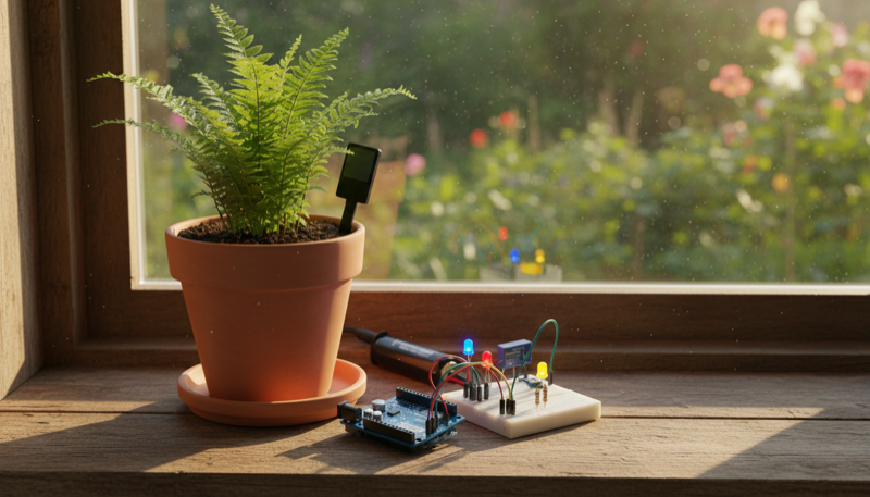
A smart plant monitor that checks soil moisture, temperature, and light, then uses color-coded LEDs to tell you what your plant needs.
Components:
- Arduino Uno R3
- Capacitive Soil Moisture Sensor (v1.2 or v2.0)
- DHT11 Temperature and Humidity Sensor
- Photoresistor (LDR)
- 3x LEDs (blue for water, red for temperature, yellow for light)
- 3x 220 ohm Resistors
- 1x 10K ohm Resistor (for LDR voltage divider)
- Solderless Breadboard
- Jumper Wires
- USB Cable
Build it:
- Wire the capacitive soil moisture sensor: VCC to 5V, GND to GND, analog output to an analog input pin (e.g., A0)
- Wire the DHT11 sensor: VCC to 5V, GND to GND, data pin to a digital pin. Install the DHT library
- Wire the photoresistor in a voltage divider with the 10K resistor, and connect the midpoint to an analog input pin (e.g., A1)
- Wire the three LEDs to digital output pins, each through a 220 ohm resistor: blue for "needs water," red for "too hot/cold," yellow for "needs more light"
- Install the Arduino IDE and add the DHT sensor library
- Write a sketch that reads all three sensors in a loop. Compare each reading to a threshold: if soil moisture is low, turn on the blue LED. If temperature is outside a healthy range, turn on the red LED. If light is too low, turn on the yellow LED
- Print the raw sensor values to Serial Monitor so you can calibrate the thresholds for your specific plant
- Stick the moisture sensor into the soil, position the light sensor near the plant, and mount the rest on a breadboard next to the pot
- Let the kids name their Plant Guardian and keep a log of what they learn about their plant's needs
These are all real projects that actually do something useful or fun when they're done. Each one teaches wiring, coding, and problem-solving. Click into any project for the full guide with code, wiring diagrams, and printable instructions.
Happy making!
Looking for a hands-on starting point? Our auto-nightlight guide is a great first project for kids, using a light sensor and just a few components.
Want projects with guaranteed finish times? See our 5 weekend projects you can complete in 2 hours. For more ideas sorted by age group, browse our Arduino projects with kids roundup.